参数配置
为了简化描述,本节可能会将 AIC_RTP_X_PLATE 和 AIC_RTP_Y_PLATE 分别简称为 X_PLATE 和 Y_PLATE。
驱动配置
-
在 Luban-Lite 根目录下执行
scons --menuconfig,进入 menuconfig 的功能配置界面,按如下选择,打开 RTP 模块依赖的 DE 驱动和 MPP。:Board options ---> [*] Using Graphics Engine (GE) [*] Using Video Engine (VE) Drivers options ---> Peripheral ---> Touch Panel Support ---> RTP touch panel options ---> [*] Using touch panel RTP (18) The sample period of RTP(in cycle mode) [AIC_RTP_PERIOD_MS] (800) The pressure threshold of RTP [AIC_RTP_MAX_PRESSURE] (235) The x-plate value of RTP touchscreen [AIC_RTP_X_PLATE] (665) The Y-plate value of RTP touchscreen [AIC_RTP_Y_PLATE] (0x4f00004f) The precharge delay of RTP [AIC_RTP_DELAY] Local packages options---> ArtInChip packages options---> [*]aic-mpp - 根据选择的 RTP 较准方式,执行不同的配置操作:
-
若使用显示模块进行 RTP 校准,可参考 Display 的 menuconfig 配置 章节。
-
当使用 RT-Thread 内核时,RTP 驱动需要依赖 RT-Thread 的 Touch 设备驱动框架,也是在 menuconfig 界面中打开:
Rt-Thread options ---> RT-Thread Components ---> Device Drivers ---> [*] Using Touch device drivers [ ] touch irq use pin irq提示:-
为了简化使用,Using RTP 会自动打开 RT-Thread 的 Touch 设备驱动框架。
-
勿勾选
touch irq use pin irq。RTP 当前采用内部控制器,不需要单独引脚进行中断控制。
-
-
RTP 自定义参数
RTP 驱动在 menuconfig 中提供了下列扩展参数,方便用户根据板级硬件设计来进行调整:
|
参数名称 |
类型 |
取值范围 |
功能说明 |
|---|---|---|---|
|
AIC_RTP_PERIOD_MS |
正整数 |
[18, 1000] |
周期采样模式下的周期值,单位为 ms。 |
|
AIC_RTP_MAX_PRESSURE |
正整数 |
[1, 4095] |
压感过滤值,超过此值的坐标事件会被忽略。 AIC_RTP_MAX_PRESSURE:若希望降低屏幕灵敏度需,设小该数值,反之则增大。压感值越大,映射为压力越小。当触点压力小于该参数所对应的压力时,该点即会被过滤掉,从而起到降低灵敏度作用。 |
|
AIC_RTP_X_PLATE |
正整数 |
> 0 |
需要实测屏幕 X 方向的电阻,用于计算压感值。 |
|
AIC_RTP_Y_PLATE |
正整数 |
> 0 |
需要实测屏幕 Y 方向的电阻,用于计算压感值。 |
|
AIC_RTP_DELAY |
十六进制 |
[0 0xffffffff] |
按压检测预充电延时,用于设置屏幕电容的充电时长。当屏幕越大时,电容充电时长应适当调大。 |
不同的参数组合,可以让 RTP 工作在不同的采样模式,对应关系如下:
|
模式 |
子模式 |
采样点 |
用户配置的参数组合 |
备注 |
|---|---|---|---|---|
|
自动模式 |
Auto1 非周期 |
XN, YN |
无 |
- |
|
Auto1 周期 |
AIC_RTP_PERIOD_MS |
- |
||
|
Auto2 非周期 |
XN, YN, ZA, ZB |
AIC_RTP_X_PLATE, AIC_RTP_Y_PLATE |
- |
|
|
Auto2 周期 |
AIC_RTP_X_PLATE, AIC_RTP_PERIOD_MS, AIC_RTP_Y_PLATE |
缺省模式。 受限于 RTOS 的任务管理手段,目前只支持 Auto2 周期 模式。 |
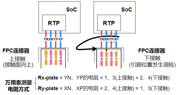
触摸屏的电阻手测方法
以下是测量触摸屏电阻值的方法示例,原理图中触摸屏的四个引脚分别为 PA11(YN)、PA10(XN)、PA09(YP) 和 PA08(XP)。测量过程中需根据电路原理图中 RTP 的引脚顺序,确定 XN、XP、YN、YP 在屏幕的位置。
触摸屏的电阻自测方法
- 在 RT-Thread 的 menuconfig 中打开 RTP
example:
Drivers options ---> Drivers examples ---> [*] Enable RTP driver test command - 执行
test_rtp_adc命令:执行下列命令查看命令帮助:
test_rtp_adc -h输出示例如下:Usage: test_rtp_adc [options]: -r, --read <chan> # 选择下面 CHAN-ID 对应通道作为 ADC 采样通道 -t, --voltage\t\tModify default voltage # 配置 ADC 基准参考电压 -n, --number\t\tSet the number of samples # 配置采样点数 -g, --get\t\tGet the panel resistance # 获取电阻屏电阻 -s, --show\t\tshow saved resistance values # 打印所保存的电阻值 -h, --help Example1: test_rtp_adc -r 1 -n 10 -t 3.3 Example2: test_rtp_adc -g Example3: test_rtp_adc -s CHAN-ID: [0] Y- [1] X- [2] Y+ [3] X+test_rtp_adc-r 1 -n 2 -t 3.3
输出示例如下所示:
[0] ch1: 1764    # [采样点序数] ch 通道号 : ADC 值
voltage:1.4792 v # ADC 对应电压值
[1] ch1: 1764
voltage:1.4792 v
test_rtp_adc -g输出示例如下所示:
=== First Measurement ===
[0] ch0: 633, voltage: 0.4637 v
[1] ch0: 634, voltage: 0.4644 v
[2] ch0: 634, voltage: 0.4644 v
...
Rx = 240 Ω, Ry = 685 Ω
test_rtp_adc -s输出示例如下所示:
=== Saved Resistance Values ===
...
Rx = 240 Ω
Ry = 685 Ω
RTP 校准
Drivers options  --->
    Drivers examples  --->
        [*] Enable RTP driver test command
test_rtp_draw -cTop left : X = 50 Y = 50
Calibration: X = 958, Y = 90
Top right : X = 974 Y = 50
Calibration: X = 69, Y = 86
Bot right : X = 974 Y = 550
Calibration: X = 61, Y = 526
Bot left : X = 50 Y = 550
Calibration: X = 876, Y = 535
Center : X = 512 Y = 300
Calibration: X = 522, Y = 303RTP 屏幕参数
这里记录测试过的几款屏幕参数,主要是 X、Y 方向的电阻值,对应参数中的 X_PLATE、Y_PLATE:
屏型号 |
分辨率 |
板子类型 |
X_PLATE |
Y_PLATE |
备注 |
|---|---|---|---|---|---|
LCD 屏 |
800x480 |
per1 |
235 |
902 |
- |
LVDS 屏 |
1024x600 |
per1 |
702 |
236 |
- |