烧录内置 SPI NOR
针对支持合封 NOR Flash 的芯片,设备生产厂商可能希望在主控芯片焊接到板子前对于合封 NOR 进行镜像数据烧录。这种离线烧录方法,可以确保芯片在出厂前已经包含了必要的固件或应用程序。
本节介绍如何使用外部烧录器对合封 NOR 进行离线烧录,适用于支持合封 NOR Flash 的匠芯创芯片。
-
烧录内置的 SPINOR
固件处理
-
烧录 BootLoader:用于驱动烧录板,完成烧录工作,并通过 GPIO 等提示烧录成功。
-
量产 BootLoader:即客户的量产 BootLoader,用于驱动客户量产板。
目前的 image_cfg.json 文件支持对这两个 BootLoader 进行配置。
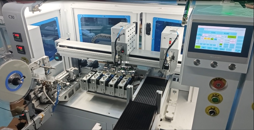
机器烧录
机器烧录具有成本低、效率高、时间短等优点,但同时对烧录的量有要求,因此投资比较大,一般都和三方烧录公司合作。
AIC 拥有合作的烧录公司,具备完整的配套工作体系和标准工作流程。由于机器烧录适合大批量生产,首次与烧录厂合作时,建议提前与 AIC 或者经销商进行充分沟通。
-
烧录板上配备 TF 卡槽,用于存储烧录用固件。
-
烧录机器的机械臂负责完成芯片的吸取和放置操作。
-
芯片准确放置到位后,烧录机器控制烧录板的 TypeC 接口上电。
-
上电后,直接启动 TFCard 烧录流程。
-
烧录完成后,烧录板通过一个 GPIO(PA1) 端口向烧录机器发送通知。
-
烧录机器下电,吸取烧录好的芯片并放置到托盘中。
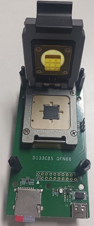
手工烧录
手工烧录可以作为机器烧录的补充,适用于少量芯片的烧录工作。
AIC 提供可以进行手工烧录的电路板。
-
烧录板上有 TF 卡槽存储烧录用固件。
-
借助工具,手工完成芯片的吸取和放置。
-
合上烧录盖后上电,直接启动 TFCard 烧录流程。
-
可通过串口信息或者 PA1(UART RX)端口,判断烧录是否成功。
-
烧录完成后断电,吸取烧录好的芯片并放置到托盘中,并进行下一颗芯片的烧录。
固件处理
-
烧录 BootLoader:用于驱动烧录板,完成烧录工作,并通过 GPIO 等提示烧录成功。
-
量产 BootLoader:即客户的量产 BootLoader,用于驱动客户量产板。
目前的 image_cfg.json 文件支持对这两个 BootLoader 进行配置。
-
按下面步骤配置烧录板。
烧录板的配置应遵循尽量简洁的原则:-
通过 bm 命令打开 BootLoader 的配置界面。
-
在 Board options 界面打开如下配置项,其他配置项可以关闭。
-
Uart0
-
Using SPI0
-
Using SDMC1
-
Using DMA
-
Using WRI
-
Using RTC
-
Using Watchdog
-
Using Efuse/SID
-
Using Syscfg: 打开
-
Using Syscfg: 同时打开 SiP Flash Enable 和 SYSCFG LDO1X enable
-
-
在 中打开 Upgrading by SD Card。
-
-
GPIO 控制
由于 GPIO 默认为低电平,无需进行预控制操作,直接在代码中进行逻辑处理即可。具体代码修改如下:
-
PA4 为烧录成功指示灯,显示绿灯
-
PA5 为烧录失败指示灯,显示红灯
-- a/application/baremetal/bootloader/cmd/aicupg.c +++ b/application/baremetal/bootloader/cmd/aicupg.c @@ -25,6 +25,7 @@ #include <hal_rtc.h> #include <wdt.h> #include <progress_bar.h> +#include <aic_hal_gpio.h> #ifdef LPKG_CHERRYUSB_HOST #include <usbh_core.h> #endif @@ -499,6 +500,19 @@ static int do_fat_upg(int intf, char *const blktype) char protection[PROTECTION_PARTITION_LEN] = {0}; ulong actread, offset, bootlen; char *file_buf; + u32 pin_ok; + u32 pin_fail; + + pin_ok = hal_gpio_name2pin("PA.4"); + hal_gpio_set_func(GPIO_GROUP(pin_ok), GPIO_GROUP_PIN(pin_ok), 1); + hal_gpio_direction_output(GPIO_GROUP(pin_ok), GPIO_GROUP_PIN(pin_ok)); + hal_gpio_set_value(GPIO_GROUP(pin_ok), GPIO_GROUP_PIN(pin_ok), 0); + + pin_fail = hal_gpio_name2pin("PA.5"); + hal_gpio_set_func(GPIO_GROUP(pin_fail), GPIO_GROUP_PIN(pin_fail), 1); + hal_gpio_direction_output(GPIO_GROUP(pin_fail), GPIO_GROUP_PIN(pin_fail)); + hal_gpio_set_value(GPIO_GROUP(pin_fail), GPIO_GROUP_PIN(pin_fail), 0); + if (!strcmp(blktype, "udisk")) { /*usb init*/ @@ -524,18 +538,21 @@ static int do_fat_upg(int intf, char *const blktype) ret = mmc_init(intf); if (ret) { printf("sdmc %d init failed.\n", intf); + hal_gpio_set_value(GPIO_GROUP(pin_fail), GPIO_GROUP_PIN(pin_fail), 1); return ret; } ret = aic_fat_set_blk_dev(intf, BLK_DEV_TYPE_MMC); if (ret) { pr_err("set blk dev failed.\n"); + hal_gpio_set_value(GPIO_GROUP(pin_fail), GPIO_GROUP_PIN(pin_fail), 1); return ret; } #else pr_err("sdcard upgrade disabled.\n"); #endif } else { + hal_gpio_set_value(GPIO_GROUP(pin_fail), GPIO_GROUP_PIN(pin_fail), 1); return ret; } @@ -575,6 +592,9 @@ static int do_fat_upg(int intf, char *const blktype) printf("\nPlug-out SDCard/UDISK to reboot device.\n"); printf(" CTRL+C exit to command line.\n"); + /* Config PA1 output high level */ + hal_gpio_set_value(GPIO_GROUP(pin_ok), GPIO_GROUP_PIN(pin_ok), 1); + /* Reboot when SDCard/UDISK plug-out */ while (1) { /* If failed to read data, reboot */ @@ -595,6 +615,7 @@ static int do_fat_upg(int intf, char *const blktype) } err: + hal_gpio_set_value(GPIO_GROUP(pin_fail), GPIO_GROUP_PIN(pin_fail), 1); if (file_buf) aicos_free_align(0, file_buf); #endif -
-
完成上述代码修改后,需对 BootLoader 进行编译。编译后的 BootLoader 将作为开发板专用的烧录 BootLoader,放置到工程的 pack 目录中进行单独管理,具体操作如下:注:
烧录 BootLoader 的分区配置 (image_cfg.json) 必须使用量产分区。
-
在 output/开发板_rt-thread_helloworld/images/ 目录下,手动将 BootLoader.aic 备份为 BootLoader-updater.aic。
cp output/g73x_scan_rt-thread_helloworld/images/bootloader.aic target/g73x/scan/pack/bootloader-updater.aic -
在 target/soc/开发板/pack/image_cfg.json 文件中,将烧录使用的 bootloader 指定为 BootLoader-updater.aic,具体修改如下:
--- a/target/g73x/scan/pack/image_cfg.json
+++ b/target/g73x/scan/pack/image_cfg.json
@@ -20,7 +20,7 @@
        },
        "updater": { // Image writer which is downloaded to RAM by USB
            "spl": {
-                "file": "bootloader.aic",
+                "file": "bootloader-updater.aic",
                "attr": ["required", "run"],
                "ram": "0x30100000"
            },
-
-
将 BootLoader 的配置文件回退到量产固件配置后,重新编译固件,即可完成量产 BootLoader 的设置。
-
经过上述配置后,量产固件已成功配置了两个 BootLoader。对于其他部分,如 OS,按照常规方式维护和编译即可,无需额外配置。