RTP 配置
内核配置
-
在 SDK 根目录下,执行下列命令,进入 kernel 的功能配置界面:
make kernel-menuconfig或使用简写命令:
make km -
在内核配置界面,按如下选择:
Linux Device Drivers Input device support [*] Touchscreens <*> ArtInChip resistive touchscreen controller support -
同时,使能 Event 接口,以便获取 Input 事件:
Linux
    Device Drivers
        Input device support
            <*> Event interface
DTS 参数配置
- RTP 自定义参数
RTP 驱动支持从 DTS 中配置的完整参数,如下表:
表 1. RTP 自定义参数 参数名称
类型
取值范围
功能说明
aic,max-pressure
正整数
[1, 4095]
最大压感值,超过此值的坐标事件会被忽略。
aic,x-plate
正整数
> 0
需要实测屏幕 X 方向的电阻,用于计算压感值。
aic,y-plate
正整数
> 0
需要实测屏幕 Y 方向的电阻,用于计算压感值。
aic,two-points
boolean
有 - 1,无 - 0
是否打开两点采样。
aic,manual-mode
boolean
有 - 1,无 - 0
是否采用手动模式。
aic,sample-period-ms
正整数
[1, 1000]
周期采样模式下的周期值,单位:ms。
aic,fuzz
正整数
[1, 32]
对坐标变化模糊处理的半径值。
表 2. RTP 采样模式和参数配置关系 模式
子模式
采样点
需要用户配置的 DTS 参数
备注
手动模式
无压感
XN, YN
manual-mode
-
无压感
XN, YN, ZA
manual-mode
x-plate
y-plate
-
XN, YN, ZA, ZB
manual-mode
x-plate
-
自动模式
Auto1 非周期
XN, YN
-
-
Auto1 周期
sample-period-ms
-
Auto2 非周期
XN, YN, ZA, ZB
x-plate
缺省模式
基于实测数据,Auto2 非周期模式在性能上表现比较平衡,所以 DTS 中会作为缺省配置。
Auto2 周期
x-plate
sample-period-ms
-
Auto3 非周期
XN, XP, YN, YP, ZA, ZB
x-plate, y-plate
two-points
-
Auto3 周期
x-plate,
y-plate
two-points
sample-period-ms
-
Auto4 非周期
XN, XP, YN, YP, ZA, ZB, ZC, ZD
x-plate
two-points
-
Auto4 周期
x-plate
two-points
sample-period-ms
-
注:- 为便于表示,所有参数名称均省略了“aic,” 前缀。
-
对于 Auto2 模式,如果用户配置了 plate,ZB 数据将驱动被忽略,压感计算 时采样公式 2。
- D211 的配置common/d211.dtsi 中的参数配置:
rtp: rtp@19252000 {
    compatible = "artinchip,aic-rtp-v1.0";
    reg = <0x0 0x19252000 0x0 0x1000>;
    interrupts-extended = <&plic0 93 IRQ_TYPE_LEVEL_HIGH>;
            clocks = <&cmu CLK_RTP>, <&cmu CLK_APB1>;
    clock-names = "rtp", "pclk";
    resets = <&rst RESET_RTP>;
};
xxx/board.dts 中的参数配置:&rtp { aic,max-pressure = <800>; aic,x-plate = <235>; pinctrl-names = "default"; pinctrl-0 = <&rtp_pins>; status = "okay"; };上述示例中:-
选用了 Auto2 的 Single Piont 模式,因此只用到 RTP 驱动的部分参数。
-
x-plate 和 plate 两个参数需要根据触摸屏的电阻实测值来设置。
-
触摸屏的电阻实测方法
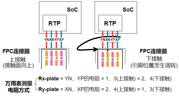
-
原理图中触摸屏的四个引脚为 PA11(YN)、PA10(XN)、PA09(YP) 和 PA08(XP)。
-
测量过程中需根据电路原理图中 rtp 的引脚顺序,确定 XN、XP、YN、YP 在屏幕的位置。
几款 RTP 屏幕的参数
这里记录测试过的几款屏幕参数,主要是 X、Y 方向的电阻值,对应 DTS 中的 plate、y-plate:
屏型号 |
分辨率 |
板子类型 |
x-plate |
y-plate |
|---|---|---|---|---|
LCD 屏 |
800x480 |
per1 |
235 |
902 |
LVDS 屏 |
1024x600 |
per1 |
702 |
236 |