获取和配置触摸 IC 关键信息
本节旨在通过不同芯片的规格书,介绍如何获取触摸 IC 的关键信息,包括但不限于以下内容:
- 从机设备地址
- 触摸点 ID 号
- X 轴坐标值
- Y 轴坐标值
- 触摸点个数
- 硬件上电时序
从机设备地址
获取触摸芯片的从机地址是主控和外设通信的关键步骤,下面是两种常见的获取从机设备地址的方法:
-
硬件扫描:
在硬件连接正常的前提下可以通过i2c-tools扫描硬件获取从机设备的地址:- 使能
i2c-tools测试工具。Local packages options ---> Third-party packages options ---> [*] i2c-tools: a collection of i2c tools including scan/read/write - 在串口执行
i2c scan i2c interface命令,例如:i2c scan i2c1i2c interface 需按照实际使用的接口进行设置。
以 GT911 为例,系统输出示例如下,表示 当前的从机地址为 0x5D:00 01 02 03 04 05 06 07 08 09 0A 0B 0C 0D 0E 0F 00: -- -- -- -- -- -- -- -- -- -- -- -- -- -- -- -- 10: -- -- -- -- -- -- -- -- -- -- -- -- -- -- -- -- 20: -- -- -- -- -- -- -- -- -- -- -- -- -- -- -- -- 30: -- -- -- -- -- -- -- -- -- -- -- -- -- -- -- -- 40: -- -- -- -- -- -- -- -- -- -- -- -- -- -- -- -- 50: -- -- -- -- -- -- -- -- -- -- -- -- -- 5D -- -- 60: -- -- -- -- -- -- -- -- -- -- -- -- -- -- -- -- 70: -- -- -- -- -- -- -- -- -- -- -- -- -- -- -- --
注:i2c-tools也可以用于检测主控与外设之间的硬件连接关系是否正常。如果执行上述命令后扫描不到任何从机地址,则需检查硬件是否正常以及 I2C 是否有外部上拉电阻等情况。 - 使能
-
从对应 IC 的规格书中获取信息。
通常情况下,IC 规格书会按照以下方式列示相关从机地址:-
直接提供 7 位从机地址。例如,GSL3676 的规格书中列示了 7 位从机地址为 0x40:
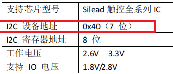
所以在设置从机地址时直接设置位 0x40 即可。
-
二种是包括了读写位的地址,例如 GT911 的规格书给出的从机地址会有两个,并且两个地址的差值为 1,那就说明这个地址是 8 位的,包括了读写位:

所以在设置从机地址的时候我们需要将地址右移 1 位,才是真实从机地址,这里的 0xBA,0xBB 右移 1 位的地址为 0x5D。
-
触摸点 ID 号
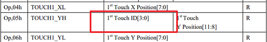
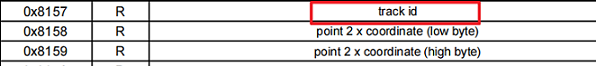
对于 ID 号的描述一般是
track id 或者是 Touch ID 等,包含 ID
字样的字段:- Track ID 示例:
off_set = read_index * C145HAX01_POINT_INFO_LEN; read_id = (read_buf[off_set + 3] >> 4) & 0x0f; pre_id[read_index] = read_id; input_x = ((read_buf[off_set + 1] & 0x0f) << 8) | read_buf[off_set + 2]; input_y = ((read_buf[off_set + 3] & 0xf) << 8) | read_buf[off_set + 4]; - Touch ID 示例:
 off_set = read_index * 8;
 read_id = read_buf[off_set] & 0x0f;
 pre_id[read_index] = read_id;
 input_x = read_buf[off_set + 1] | (read_buf[off_set + 2] << 8); /* x */
 input_y = read_buf[off_set + 3] | (read_buf[off_set + 4] << 8); /* y */
 input_w = read_buf[off_set + 5] | (read_buf[off_set + 6] << 8); /* size */
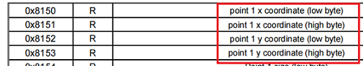
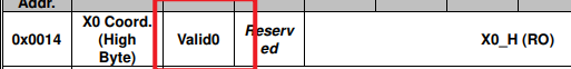
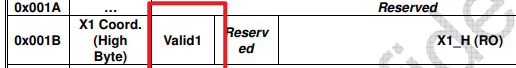
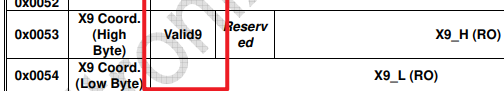
XY 坐标计算
常见 CTP 的 XY 在 16 bit 的数据范围内,一般由两个字节组合而成,需要通过一定的逻辑计算出真实的坐标值:
 off_set = read_index * 8;
 read_id = read_buf[off_set] & 0x0f;
 pre_id[read_index] = read_id;
 input_x = read_buf[off_set + 1] | (read_buf[off_set + 2] << 8); /* x */
 input_y = read_buf[off_set + 3] | (read_buf[off_set + 4] << 8); /* y */
 input_w = read_buf[off_set + 5] | (read_buf[off_set + 6] << 8); /* size */
 off_set = read_index * 8;
off_set = read_index * 8;
read_id = read_buf[off_set] & 0x0f;
pre_id[read_index] = read_id;
input_x = read_buf[off_set + 1] | (read_buf[off_set + 2] << 8); /* x */
input_y = read_buf[off_set + 3] | (read_buf[off_set + 4] << 8); /* y */
input_w = read_buf[off_set + 5] | (read_buf[off_set + 6] << 8); /* size */触摸点个数
触摸事件可分为按下、移动和抬起,事件的获取是通过当前触摸点个数与上一次触摸点个数比较得到的,下面是几种比较常见的获取当前触摸点个数的方式:
-
从寄存器可以直接获取当前的触摸点个数:

touch_num = point_status & 0x0f; /* get point num */ -
通过每根手指的触摸事件间接计算:
 cmd[0] = (rt_uint8_t)((ST77922_TOUCH_INFO >> 8) & 0xFF);
 cmd[1] = (rt_uint8_t)(ST77922_TOUCH_INFO & 0xFF);
 /* read point num is touch_num */
 if (st77922_read_regs(&st77922_client, cmd, read_buf, sizeof(read_buf)) != RT_EOK) {
     rt_kprintf("read point failed\n");
     read_num = 0;
     goto __exit;
 }

 for (i = 0; i < ST77922_MAX_TOUCH; i++) {
     num_valid = ((read_buf[7 * i + 4] & 0x80) != 0) ? 1 : 0;
     touch_num += num_valid;
 }
TP 硬件上电时序
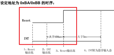
 rt_pin_mode(*(rt_uint8_t *)cfg->user_data, PIN_MODE_OUTPUT);
 rt_pin_write(*(rt_uint8_t *)cfg->user_data, PIN_LOW);
 rt_thread_delay(10);
 // irq output 0
 rt_pin_mode(cfg->irq_pin.pin, PIN_MODE_OUTPUT);
 rt_pin_write(cfg->irq_pin.pin, PIN_LOW);
 rt_thread_delay(2);
 // rst output 1
 rt_pin_mode(*(rt_uint8_t *)cfg->user_data, PIN_MODE_OUTPUT);
 rt_pin_write(*(rt_uint8_t *)cfg->user_data, PIN_HIGH);
 rt_thread_delay(5);
 // rst input
 rt_pin_mode(*(rt_uint8_t *)cfg->user_data, PIN_MODE_INPUT);
 //irq output 0
 rt_pin_mode(cfg->irq_pin.pin, PIN_MODE_OUTPUT);
 rt_pin_write(cfg->irq_pin.pin, PIN_LOW);
 rt_thread_delay(50);
 rt_pin_mode(cfg->irq_pin.pin, PIN_MODE_INPUT);